
The tunnel line itself arriving at the factory is only half the matter. Exhaust ducts, liquid nitrogen supply piping, the connections at both infeed and outfeed ends with upstream and downstream processes, and the space needed for lifting maintenance—if these four areas are not clearly defined on site, no matter how precisely the mesh belt speed is adjusted, a stable freezing rhythm cannot be achieved. Kunning Cryo DKN-LFT series tunnel lines come with liquid nitrogen proportional valves, upper and lower injection devices, and exhaust gas extraction ports at the infeed and outfeed ends. Liquid nitrogen storage tanks and exhaust ducts are provided on site. Below, the interface conditions and selection basis for these areas are listed item by item.
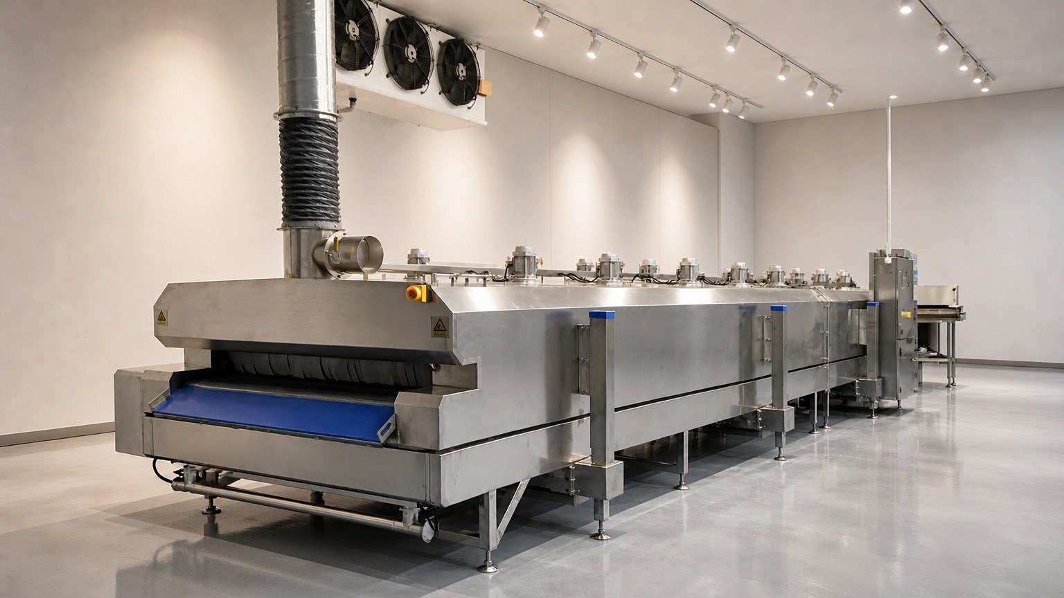
Equipment Overview
The DKN-LFT series is a mesh belt continuous tunnel line with an overall lifting body, used for categories requiring continuous feeding and single-piece placement before freezing. The equipment consists of four parts: body, conveying system, freezing system, and control system. Working temperature is -150℃ to room temperature, with temperature control accuracy of ±2℃.
The freezing principle is the superposition of heat absorption from liquid nitrogen vaporization and sensible heat of low-temperature nitrogen gas. Liquid nitrogen is delivered through proportional valves to nozzles inside the tunnel, where spraying and vaporization carry away heat; low-temperature long-shaft motors at the top with nylon axial flow fans blow cold air into a circulating wind field, making the temperature above and below the mesh belt tend to be uniform. At no load, the tunnel can cool down at approximately 10℃ per minute. The actual cooling curve is related to loading capacity and feed temperature.
Models and Parameters
The four models differ considerably in mesh belt dimensions, external dimensions, and power. When selecting, first look at single-piece placement dimensions and capacity, then at available workshop length.
| Model | Mesh Belt Dimensions (L×W) | Equipment External Dimensions (L×W×H) | Total Power | Infeed to Outfeed Cycle | Freezing Capacity |
|---|---|---|---|---|---|
| DKN-LFT-0908 | 8000 × 900 mm | 8000 × 1750 × 1670 mm | Approx. 15 kW | Confirm per order | Confirm per order |
| DKN-LFT-1206 | 6000 × 1200 mm | 6000 × 2200 × 1750 mm | 9 kW | 6~30 minutes adjustable | Confirm per order |
| DKN-LFT-1212 | 12000 × 1200 mm | 12000 × 2250 × 1670 mm | 18 kW | 5~25 minutes adjustable | 1 m³/h |
| DKN-LFT-1612 | 12000 × 1600 mm | 12000 × 2700 × 1950 mm | 26 kW | 8~40 minutes adjustable | Confirm per order |
Basic parameters shared by all four models:
| Item | Parameter |
|---|---|
| Working temperature | -150℃ ~ room temperature |
| Temperature control accuracy | ±2℃ |
| No-load cooling rate | Approx. 10℃ per minute |
| Power supply specification | 380V / 50Hz |
| Liquid nitrogen supply pressure | 5~8 bar (liquid nitrogen storage tank provided on site) |
| Oxygen concentration detection setpoint | 19.5% ~ 21.5% |
Main Configuration
Per system description, component brands and specific models are not detailed in external materials.
- Body: Inner and outer cavities are formed from food-grade stainless steel plates by shearing, bending, and double-sided welding. Reinforcement ribs are added at load-bearing positions, and the ribs have undergone low-temperature foaming treatment to prevent cold air penetration; multi-layer insulated foam layer thickness is 150 mm; the bottom of the body is shallow V-shaped with a drainage outlet, allowing cleaning residue and accumulated water to discharge through the drain pipe.
- Conveying system: Food-grade stainless steel mesh belt, equipped with variable frequency speed control motor and reducer, with adaptive tensioning device to maintain operating tension at low temperatures; mesh belt linear speed is adjusted by category, corresponding to the infeed/outfeed cycles in the table above.
- Freezing system: Low-temperature proportional valve dual-valve control, switchable manually or automatically; multiple sets of stainless steel nozzles distributed above and below the mesh belt, can be opened as a whole or independently by zone, with adjustable upper and lower injection angles; top low-temperature long-shaft motors with nylon axial flow fans, single unit air volume 6000 m³/h, air pressure 65 Pa, nylon fan blades do not frost at low temperatures; exhaust gas extraction ports at infeed and outfeed ends, connected to on-site exhaust ducts.
- Control system: PLC with PID regulation, touch screen input, mesh belt speed variable frequency adjustable, can store multiple freezing processes for one-key operation; temperature measurement points use PT100 platinum resistance, one for main control, one for monitoring.
- Safety system: Emergency stop switches at infeed end, electrical cabinet, and outfeed end; oxygen concentration detector installed near the equipment, linked with liquid nitrogen on/off valve. When concentration falls below the set value, it cuts off supply, activates audible and visual alarms, and stops the equipment, while the exhaust fan continues running; when the exhaust fan fails, the equipment stops directly. If the exhaust fan does not start, the equipment does not run.
On-Site Interfaces and Supporting Facilities
This part determines whether the tunnel line can run on schedule. These four items need to be reserved in advance on site drawings.
Exhaust: The equipment has exhaust gas extraction ports at both infeed and outfeed ends. The nitrogen gas discharged by the exhaust fan needs on-site exhaust ducts routed to the outdoors. The “Safety Technical Management Guidelines for Enterprises Involving Liquid Nitrogen Quick-Freezing Tunnel Lines (Trial)” issued by the Hubei Provincial Emergency Management Department has specific requirements for this: tunnel lines should be located in independent quick-freezing rooms, with mechanical exhaust in the production area maintaining slight negative pressure; when starting up, the exhaust system should be started at least 3 minutes in advance before starting the equipment; after shutdown, the equipment stops first, and exhaust should be delayed at least 3 minutes before turning off; the exhaust system should have continuous fan current monitoring and alarms, interlocked with equipment start/stop; when the exhaust outlet temperature is below 0℃ or white mist in the production area continues to increase, immediately check for leaks (see the original guidelines at Hubei Provincial People’s Government Portal).
Liquid nitrogen supply: Equipment-side interfaces are designed for 5~8 bar liquid nitrogen. Storage tanks and delivery pipes are provided on site. According to the same guidelines, emergency shut-off valves should be installed on liquid nitrogen piping entering the workshop, and emergency stop buttons at both ends of the tunnel and the control cabinet should remain accessible; piping, fittings, and seals should be selected for low-temperature conditions.
Electricity and grounding: 380V/50Hz three-phase power supply. The equipment comes with grounding wire and circuit breaker, and a phase sequence protector inside the machine to avoid reverse operation faults caused by reversed power connection.
Maintenance and cleaning space: The body is of overall lifting type, with a lifting stroke upper limit of 550 mm and an inner cavity of 750 mm, used for parts replacement and maintenance; the height and width of the operating face are designed according to personnel working dimensions. The height of loading, tray placement, and outfeed connection equipment should be flush with the mesh belt surface, and the rhythm of upstream and downstream processes should match the infeed/outfeed cycle.
Application Scenarios
- Aquatic products: Shrimp, fish fillets, fish heads, etc., placed as single pieces and continuously passed through the tunnel, combined with individual quick freezing to reduce clumping; models with mesh belt 1200 mm and above are suitable for multi-row placement. See Capacity and Space Matching of Liquid Nitrogen Quick-Freezing Tunnels in Aquatic Product Processing.
- Prepared dishes and ready meals: Frequent batch changes, use storable processes for one-key retrieval of freezing parameters, infeed/outfeed cycle selected by packaging thickness.
- Meat and poultry cuts: For continuous large-volume applications, use the 12-meter mesh belt model, with the front end connected to the cutting line and the rear end connected to packaging.
- Pastry and baking semi-finished products: Suitable for short-cycle freezing, reducing surface cracking. For production scheduling and line layout, see Line Layout of Pastry Quick-Freezing Section.
For mesh belt dimensions and configurations of the four models, see Liquid Nitrogen Quick-Freezing Tunnel Product Page; for the relationship between mesh belt speed and freezing cycle, see How to Determine the Freezing Cycle of Liquid Nitrogen Quick-Freezing Tunnels.
Frequently Asked Questions
What supporting facilities need to be provided on site for the tunnel line?
Liquid nitrogen storage tank, liquid nitrogen delivery pipes, exhaust ducts, and power supply and site meeting 380V/50Hz. Storage tank capacity is determined by actual consumption; the equipment itself does not include a storage tank.
Why must the exhaust system be interlocked with the equipment?
Nitrogen gas is denser than air and will accumulate at the bottom of the tunnel and low areas of the workshop. When oxygen concentration drops, it is not easily noticed. Interlocking exhaust with equipment start/stop and providing continuous fan current monitoring allows timely shutdown when the fan stops; installing emergency shut-off valves on liquid nitrogen piping entering the workshop allows direct liquid cutoff when concentration is abnormal. These items are all written in the “Safety Technical Management Guidelines for Enterprises Involving Liquid Nitrogen Quick-Freezing Tunnel Lines (Trial)”.
How to choose mesh belt dimensions among the four models?
First calculate the width occupied by single-piece placement, then determine how many pieces need to pass per hour. DKN-LFT-1206 mesh belt 6000 × 1200 mm is suitable for workshops with limited length and single-row or double-row placement; DKN-LFT-1212 and DKN-LFT-1612 have mesh belt length 12000 mm, suitable for continuous large-volume production. The 1612 has mesh belt width 1600 mm, making multi-row placement less prone to crowding.
How much space should be reserved for equipment maintenance?
The body can be lifted as a whole, with a lifting stroke upper limit of 550 mm and inner cavity of 750 mm; reserving a mesh belt replacement passage and operating face working space is sufficient. The lifting system has an automatic locking device and manual safety pin.
What controls the core temperature of frozen products?
It relies on the coordination of mesh belt speed and liquid nitrogen spray volume, as well as the uniformity of the circulating wind field. The equipment can store multiple freezing processes. Parameter combinations are determined after trial production by category on site; no-load cooling at approximately 10℃ per minute can serve as a debugging reference, and after mass production, the measured core temperature curve prevails.
Specific interface dimensions, supporting piping, and site conditions are confirmed per order. To verify connection positions against workshop floor plans, leave a message at the Contact Page.
Detail pages for this series
The models below have complete technical documentation; open a model to see its full specifications and configuration.
- DKN-LFT-0908 — Liquid nitrogen freezing tunnel
- DKN-LFT-1206 — Liquid nitrogen freezing tunnel
- DKN-LFT-1212 — Liquid nitrogen freezing tunnel
- DKN-LFT-1612 — Liquid nitrogen freezing tunnel