
For the same liquid nitrogen quick freezing cabinet freezing the same batch of product, the liquid nitrogen meter reading can differ by a noticeable margin between two runs. There is no “consumption per unit” item in the equipment parameter table, because liquid nitrogen consumption is jointly determined by how much heat the product must carry away, how the load is arranged, how many times the door is opened, and how the parameters are set. To bring it under control, first see clearly the two heat accounts, then manage the several variables on site.
Consumption Is Determined by Two Heat Accounts: Product Heat Release and On-Site Cold Loss
The heat released as the product drops from the inlet temperature to the target core temperature is calculated in three stages; on site, an additional portion of cooling capacity is lost.
| Heat item | Content | Affected by |
|---|---|---|
| Pre-cooling stage sensible heat | From inlet temperature down to the product freezing point | Inlet temperature, product mass, specific heat |
| Freezing stage latent heat | Heat released when free water freezes (water about 334 kJ/kg) | Moisture content, load quantity |
| Deep-freezing stage sensible heat | From freezing point down to target core temperature | Target core temperature, specific heat |
| On-site cold loss | Door-opening spillage, cabinet heat leakage, cold air carried away by exhaust, piping loss | Operating habits, door seals and insulation, exhaust settings |
The heat that liquid nitrogen can carry away is the latent heat of vaporization (about 199 kJ/kg) plus the sensible heat of the low-temperature nitrogen gas as it warms up. Adding up the three stages of product heat release and dividing by the usable heat absorption of liquid nitrogen gives the theoretical lower limit for this equipment freezing this batch; the actual reading is this lower limit multiplied by a cold loss coefficient. The coefficient is tied to the workshop, loading pattern, and door-opening habits, and can only be calibrated, not calculated.
Six Common On-Site Factors That Push It Up
| Phenomenon | Result | Control action |
|---|---|---|
| Inlet temperature on the high side | Liquid nitrogen is first used on the front-stage sensible heat, reducing the cooling capacity available for the freezing stage | Pre-cool in the preceding process, or load in batches |
| Tray spacing too small, loading too dense | Cold air cannot reach the gaps between trays, core reaches target slowly | Spread out according to rack layer height, leave air flow channels |
| Single batch exceeds the equipment’s matched load | Temperature inside the cabinet recovers slowly, liquid supply time lengthens | Arrange in batches according to model load capacity |
| High door-opening frequency, long door-opening time | Cold air spills out, cabinet must be re-cooled after temperature recovery | Centralize loading and unloading, reduce mid-process retrieval |
| Temperature set lower than process requires | Product over-frozen, extra liquid nitrogen consumed | Calibrate according to product thickness and target core temperature |
| Exhaust volume noticeably too large | Low-temperature nitrogen gas is drawn away, cooling capacity not fully used | Match fan air volume to nitrogen gas generation rate |
What Controllable Points Exist on the Equipment Side
The more sufficient the heat exchange conditions, the closer the liquid nitrogen usage for the same product heat release approaches the theoretical lower limit. The adjustable points on the equipment side are concentrated in several areas:
- Liquid supply control: Flow control valve with a porous liquid nitrogen disperser; liquid nitrogen is broken up and vaporized by fans after being split and sprayed, directly impacting the product surface; the control system can supply liquid in stages, operating step by step for cooling and holding.
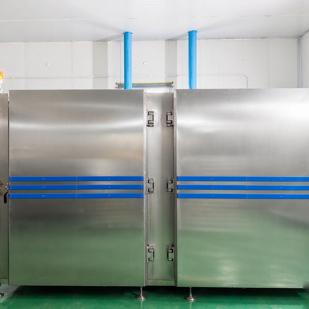
- Air field: External low-temperature-resistant long-shaft motor with multi-blade axial flow fan, air speed up to 10 m/s, guide plates press cold air toward the gaps between trays, allowing the interior of the load to also participate in heat exchange. This type of structure is seen in the liquid nitrogen quick freezing cabinet series models.
- Insulation and sealing: 150 mm low-temperature foamed insulation layer, ultra-low-temperature sealing rings maintain flexibility at low temperatures, reducing heat leakage at cabinet connections.
- Exhaust: Exhaust volume is not better the larger it is; match fan air volume and air change rate to the nitrogen gas generation rate per batch. For specific methods see Exhaust and Oxygen Concentration Monitoring for Liquid Nitrogen Quick Freezing Cabinets.
- Loading structure: Rack layer height spacing default 75 mm, can be designed according to product (DKN-LFC-300 can hold 40 trays at a time); smaller spacing means more capacity but narrower air channels, to be weighed against product thickness.
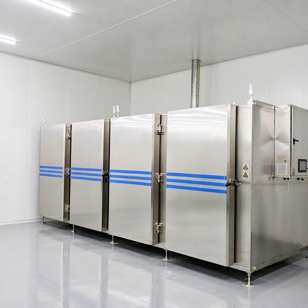
- Zoned loading: DKN-LFC-1200 has a four-zone structure, single zone 0~1200 kg; for small batches only the corresponding zone needs to be opened, without cooling the entire machine.
Continuous production lines have slightly different focus points: mesh belt upper and lower bidirectional spraying, air volume up to 6000 m³/h, air pressure 65 Pa, exhaust extraction ports at the inlet and outlet ends to reduce cold air escaping from both ends. For equipment forms see liquid nitrogen quick freezing tunnel.
Building a Plant-Specific Consumption Baseline: Record Four Numbers Per Batch
For consumption per unit to be usable for comparison, the prerequisite is consistent recording criteria. It is recommended to record four items per batch: net product weight, inlet temperature, target core temperature, liquid nitrogen meter reading; write clearly the loading pattern including rack layer count and load per tray. Divide the liquid nitrogen reading by net weight to obtain the plant’s kg liquid nitrogen/kg product baseline.
The purpose of the baseline is horizontal comparison: whether consumption per unit has decreased after changing the loading pattern for the same product, and how large the re-calibration range is after switching product categories. After switching product category, packaging, or single batch weight, the baseline must be redone once.
Whether records can be traced depends on temperature measurement and programming. Taking the liquid nitrogen quick freezing cabinet as an example, platinum resistance temperature measurement range 200℃~-200℃, one main control and one monitoring, the program can run cooling and holding in steps, and automatically alarm and cut power after completion; when switching product categories, the previous batch’s parameters can be recalled for review.
Common Questions
Can liquid nitrogen consumption be calculated accurately in advance?
The theoretical lower limit can be calculated: add up the three stages of product heat release and divide by the latent heat of vaporization of liquid nitrogen plus the sensible heat of nitrogen gas, to obtain the minimum liquid nitrogen required for this batch. Actual consumption is this number multiplied by an on-site cold loss coefficient; workshop conditions differ between plants, and the coefficient can only be obtained through trial-run calibration. Therefore at the proposal stage we give configuration recommendations based on product and batch size, and do not quote a fixed consumption per unit.
For the same cabinet, why does consumption differ greatly between two batches?
Ranked by degree of influence, it is usually one of these four items that has changed: inlet temperature, single batch load, number of door openings, target core temperature. To compare equipment or processes, first fix these four items, otherwise the readings are not comparable.
Does a fuller load save more liquid nitrogen?
A full load does not equal savings. When the load is within the equipment’s matched range, a full load dilutes the fixed consumption from door openings and heat leakage; but if stacked too densely, cold air cannot reach the gaps between trays, the time for the core to reach target lengthens, liquid supply time lengthens accordingly, and total consumption goes up instead.
Can setting a lower temperature shorten time and use less liquid nitrogen?
For thin products it causes over-freezing and consumption rises; for thick products, the time for the core to pass through the ice crystal band is limited by thickness, and no matter how low the cabinet temperature is, it cannot be much faster. What the process needs to control is the time to pass through the -1℃ to -5℃ maximum ice crystal formation band, not the equipment’s end-point temperature.
Between cabinet and tunnel, which has lower consumption per unit?
There is no uniform answer. For a single category, large batch, continuous production, the tunnel’s thin and uniform loading and fewer door openings dilute it more reasonably; for multiple varieties, small batches, frequent product changes, the cabinet is more flexible. For selection, first look at the number of categories and batch size, then discuss consumption per unit.
To look at the match between liquid nitrogen consumption and equipment according to product and batch, you can send over the product name, single batch weight, inlet temperature and target core temperature, and we will give configuration recommendations based on actual conditions: Contact Kunning Cryo
The latent heat of water freezing and the latent heat of vaporization of liquid nitrogen in this article are general physical property data; equipment parameters and structural configurations are cited from Kunning Cryo liquid nitrogen quick freezing cabinet and liquid nitrogen quick freezing tunnel technical documents, and loading data for each model is subject to the corresponding technical parameters.