
Exhaust and Oxygen Concentration Monitoring for Liquid Nitrogen Freezers: Where Nitrogen Goes and How to Set Alarm Values
When choosing a liquid nitrogen freezer, most discussions focus on cooling speed, temperature control accuracy, and hourly output in kilograms. One question is rarely asked: where does the liquid nitrogen used every day go after it vaporizes.
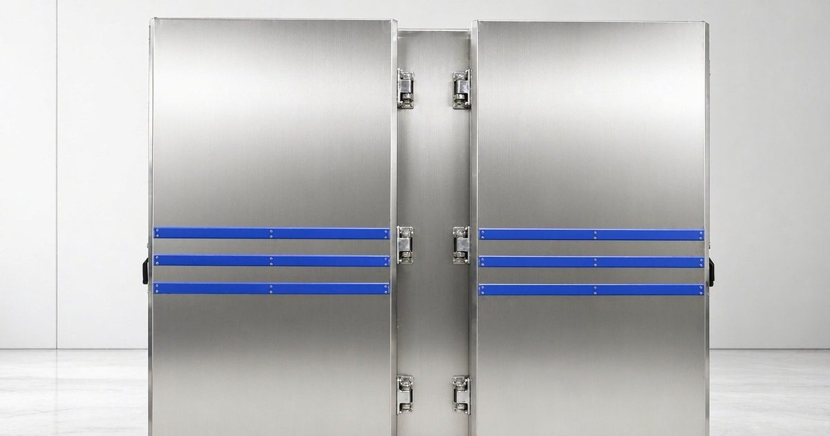
Liquid nitrogen vaporizes inside the cabinet, transfers its cooling capacity to the food, and once the temperature rises, it must be exhausted. For cabinet-type models, the exhaust port is located at the rear of the equipment, and the exhaust duct must be routed outdoors. On drawings, this step is often just a dashed line, and on site, it frequently amounts to connecting a flexible hose to a window.
The Problem
Parameter tables show temperature, but nobody manages the nitrogen
The boiling point of liquid nitrogen at atmospheric pressure is -196℃, and the operating temperature range inside the cabinet is stated as -150℃ to room temperature. This range indicates how low the equipment can go, but it does not indicate where the nitrogen goes.
The nitrogen gas produced after liquid nitrogen vaporizes has a density slightly higher than air. Under windless conditions, it settles and accumulates on the floor, in trenches, and in low-lying areas, displacing oxygen. In normal air, oxygen accounts for about 20.9%. When it drops below 19.5%, a person’s judgment begins to be affected, and further decline can lead to loss of consciousness within a short time. Oxygen deficiency has no smell and no irritation, so people cannot detect it—only instruments can.
Two things are commonly seen on site
One is that instruments are installed but not put into service. An oxygen concentration detector is mounted on the wall, but the alarm circuit is not connected, or the probe is overdue for calibration. The other is that the exhaust fan stops and nobody knows. In low-temperature workshops, fan impellers and motors are prone to frosting and freezing. When airflow drops, the motor still makes noise, and operators assume exhaust is running, while the quick-freezing room is actually accumulating nitrogen.
When these two things combine, they become a common cause of accidents. In November 2023, the Hubei Provincial Emergency Management Department issued the “Safety Technical Management Guidelines for Enterprises with Liquid Nitrogen Quick-Freezing Tunnel Lines (Trial)”, prompted by a nitrogen concentration suffocation accident in a local food company’s quick-freezing workshop in May of that year, where poor exhaust, unauthorized closure of fresh air, and failure to put oxygen concentration alarm devices into service occurred simultaneously (Source: Hubei Provincial People’s Government Portal).
The Guidelines apply to liquid nitrogen quick-freezing tunnel lines, but several practices also hold true for cabinet-type equipment: fixed oxygen concentration audible and visual alarm detectors with on-site readings shall be installed in the production area, and alarm values shall be determined according to the “Safety Regulations for Operations in Oxygen-Deficient Dangerous Environments” (GB 8958-2006); the quick-freezing area shall maintain slight negative pressure to prevent excessive nitrogen concentration from failing to disperse; the exhaust system shall be interlocked with equipment start/stop, starting exhaust before startup and delaying exhaust shutdown after stopping; the liquid nitrogen pipeline entering the workshop shall be equipped with an emergency shut-off valve; and the exhaust fan shall have continuous current monitoring and alarm. The operating pattern of cabinet-type models differs from tunnel lines (intermittent door opening, independent single-unit operation), but the path of nitrogen overflow and oxygen concentration decline is the same.
Online sources:
- Hubei Provincial People’s Government Portal, Provincial Emergency Management Department “Notice on Issuing the Safety Technical Management Guidelines for Enterprises with Liquid Nitrogen Quick-Freezing Tunnel Lines (Trial)” http://www.hubei.gov.cn/yj/202311/t20231128_4973143.shtml
- Hubei Provincial Emergency Management Department website reprinting a report from “Hubei Daily” http://yjt.hubei.gov.cn/fbjd/dtyw/mtbd/sjmt/202405/t20240523_5214441.shtml
Principles and Key Parameters
The cooling capacity of liquid nitrogen quick-freezing comes from two parts: the heat absorbed by liquid nitrogen vaporization and the sensible heat of low-temperature nitrogen gas. Based on a liquid nitrogen density of approximately 808 kg/m³ and a nitrogen gas density at normal temperature and pressure of approximately 1.25 kg/m³, 1 liter of liquid nitrogen completely vaporizes into approximately 0.65 cubic meters of nitrogen gas. For every 1 liter of liquid nitrogen entering the cabinet, approximately 0.65 cubic meters of gas needs to be exhausted from the quick-freezing room. This volume cannot be absorbed by the equipment itself and can only be exhausted.
The equipment-side structures and parameters related to exhaust and safety are as follows, taken from the technical agreements for Kunning Cryo liquid nitrogen freezers:
| Item | LFC-300 | LFC-600 | LFC-1200 | LFC-1500 |
|---|---|---|---|---|
| Structure | Cabinet, manual door | Cabinet, manual door | Cabinet, side door, four zones | Cabinet, two zones |
| Liquid nitrogen pressure | 5-8 bar | 5-8 bar | 6-8 bar | 6-8 bar |
| Liquid nitrogen flow control | Imported cryogenic liquid nitrogen solenoid valve | Imported cryogenic liquid nitrogen proportional valve | Proportional valve | Imported pneumatic cryogenic liquid nitrogen valve |
| Exhaust port location | Rear of equipment | Rear of equipment | Rear of equipment | Rear of equipment |
| Oxygen concentration detector | Not listed in technical parameter table | Not listed in technical parameter table | Set value 19.5%-21.5% | Set value 19.5%-21.5% |
| Emergency stop switch | Not listed in technical parameter table | Not listed in technical parameter table | Yes | Yes |
| Circulation motor | 3 external sealed low-temperature-resistant motors | 3 external sealed low-temperature-resistant motors | External sealed low-temperature-resistant motor | Moisture-proof, explosion-proof, low-temperature-resistant motor |
| Total power | 2.5 kW | 5 kW | 12 kW | 5 kW |
Several notes:
- The exhaust port is at the rear of the equipment so that the exhaust direction avoids the operating face and condensate does not drip onto the trays. This also determines that the exhaust duct is routed from the rear of the cabinet, and this duct section and maintenance space must be reserved on site.
- The oxygen concentration detector set value starts from 19.5%, consistent with the criteria for oxygen-deficient dangerous operations in GB 8958-2006 (this standard is referenced by the above Guidelines). The detector built into the equipment covers the area near the cabinet; alarm points at the workshop level must be arranged separately.
- Different liquid nitrogen flow control components produce different nitrogen generation rates. Solenoid valves provide on/off control, while proportional valves continuously adjust according to opening. For large-capacity multi-zone models, proportional valves make it easier to keep flow at the level required by the process.
- The circulation motor is external, using an extended stainless steel shaft to transmit power into the chamber, so that the motor does not remain in low temperature for extended periods. External motor selection should be specified according to moisture-proof, low-temperature-resistant, and if necessary explosion-proof requirements.
Selection and Configuration Points
Calculate exhaust volume first, then select the exhaust fan. Estimate nitrogen generation based on liquid nitrogen consumption per batch, determine air changes and fan airflow in combination with the volume of the quick-freezing room, and route the exhaust duct outlet outdoors. Cabinet-type equipment is mostly used intermittently; calculate based on the number of units running simultaneously, and do not assume that “they generally won’t all be on at once.”
Provide emergency shut-off on the pipeline side. Install an emergency shut-off valve on the liquid nitrogen pipeline entering the quick-freezing room, and equip the equipment end with an emergency stop button. LFC-1200 and LFC-1500 cabinets have emergency stop switches; pipeline valves are user-side accessories, and this item should be clearly stated when making on-site plans.
Place oxygen concentration probes at low positions and use two-level alarms. Nitrogen accumulates at low areas, so placing probes at breathing zone height reflects actual risk better than mounting them on the ceiling. The alarm threshold is taken as 19.5% according to GB 8958-2006, with an additional lower evacuation value. Probes should be calibrated regularly, and verification and calibration records should be entered into the equipment ledger.
The exhaust fan must be monitorable. Add continuous current monitoring and alarm to the exhaust system, so that when airflow drops, an alarm occurs first rather than waiting for people to feel dizzy. This is especially necessary in low-temperature workshops, where impeller frosting is a common phenomenon.
Set cabinet detection and room detection separately. The oxygen concentration detector built into the equipment is interlocked with the equipment and covers the area near the cabinet door; the oxygen concentration of the workshop air requires a separate fixed alarm device. The two cannot substitute for each other.
Confirm on-site conditions in advance. The liquid nitrogen storage tank is provided by the buyer; the liquid nitrogen pipeline, exhaust duct, and tank foundation must be completed before equipment arrival; the wiring between the main power line and the electrical control cabinet is laid by the buyer, and cabinet-type models are designed for 380V. The exhaust port is at the rear of the cabinet, and the exhaust duct route should avoid personnel passages.
Write door-opening frequency into operating procedures. For manual door models, the cabinet door is open for a period during each batch change, and nitrogen overflows accordingly. For production lines with many product varieties and frequent batch changes, door-opening time should be controlled, and “confirm exhaust is running before opening the door” should be written into the operating procedures.
Application Scenarios
| Industry | Typical materials | Focus of exhaust and safety configuration |
|---|---|---|
| Aquatic processing | Crayfish, fish heads, fish fillets | Liquid nitrogen use per batch is concentrated; quick-freezing room is set up independently; mechanical exhaust is sized for peak usage |
| Meat and poultry processing | Cut meat, poultry cuts | Product varieties are relatively fixed; exhaust and equipment interlock is set according to shift rhythm |
| Prepared dishes | Prepared meal packs, skin-packaged semi-finished products | Frequent batch changes, more overflow from door opening; door-opening procedures and low-position probe placement are key |
| Fruits and vegetables | Bamboo shoots, fruit and vegetable raw materials | Liquid nitrogen usage is relatively stable; size exhaust for average usage and leave margin |
| Central kitchen | Finished dishes, meal assembly | When the quick-freezing area is adjacent to the cooked food cooling area, exhaust and oxygen concentration monitoring for the two areas should be independent |
If the product is high-temperature cooked food after cooking and needs to be cooled from 80 to 90℃ down to a range such as 0 to 4℃, that falls within the application scope of forced cold air circulation blast chillers. The operation process does not generate nitrogen, and exhaust is considered according to kitchen exhaust and heat-moisture load. Refer to the application scope description for food blast chillers.
The cooling capacity of liquid nitrogen quick-freezing comes from nitrogen, and if the nitrogen cannot be exhausted, it becomes a risk. The two rows in the parameter table—liquid nitrogen pressure and oxygen concentration detector—are as worth confirming item by item when signing the technical agreement as cooling speed; exhaust volume, interlock method, and alarm points are on-site engineering matters, and the earlier they are written into the plan, the less retrofitting is needed later.
To check exhaust and oxygen concentration monitoring configuration according to your quick-freezing room conditions, you can provide the quick-freezing room area and clear height, the number of units running simultaneously, liquid nitrogen usage per batch, and the on-site layout. We will provide a configuration plan based on actual conditions: Contact Us
Image requirements: schematic of exhaust duct routing in the quick-freezing room, photo of oxygen concentration alarm installation position, location diagram of liquid nitrogen pipeline emergency shut-off valve.
Frequently Asked Questions
Where does the nitrogen from a liquid nitrogen freezer go? How are oxygen concentration alarm values set?
Nitrogen is produced after liquid nitrogen vaporizes inside the cabinet and is discharged from the exhaust port at the rear of the equipment; the exhaust duct must be routed outdoors. The set value of the equipment’s built-in oxygen concentration detector is 19.5% to 21.5%; the alarm value at the workshop level is taken as 19.5% according to the criteria of the “Safety Regulations for Operations in Oxygen-Deficient Dangerous Environments” (GB 8958-2006), with an additional lower evacuation value.
How much nitrogen does 1 liter of liquid nitrogen produce, and how is exhaust volume estimated?
Based on a liquid nitrogen density of approximately 808 kg/m³ and a nitrogen gas density at normal temperature and pressure of approximately 1.25 kg/m³, 1 liter of liquid nitrogen completely vaporizes into approximately 0.65 cubic meters of nitrogen. This volume cannot be absorbed by the equipment itself. Nitrogen generation should be estimated based on liquid nitrogen consumption per batch, and then fan airflow and air changes should be determined in combination with the volume of the quick-freezing room.
What are the differences in exhaust and safety configuration between LFC-300 and LFC-1200?
Both are cabinet-type models, and both have exhaust ports at the rear of the equipment. For LFC-300 and LFC-600, the oxygen concentration detector and emergency stop switch are not listed in the technical parameter table; for LFC-1200 and LFC-1500, the oxygen concentration detector set value is 19.5% to 21.5% and an emergency stop switch is included. For liquid nitrogen pressure, LFC-300 and LFC-600 are 5-8 bar, while LFC-1200 and LFC-1500 are 6-8 bar.