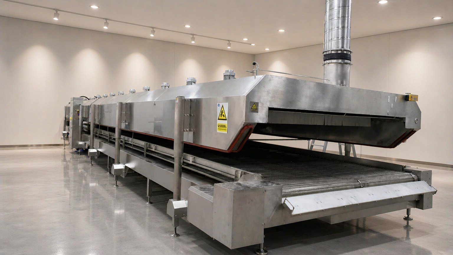
The liquid supply system of a liquid nitrogen freezer consists of three sections: tank, piping, and equipment interface. The gas consumption rate of the equipment is provided by us; the tank and piping are usually supplied by the customer or a local gas supplier. If these three sections are not aligned during the drawing review stage, problems such as mismatched interfaces, insufficient capacity, or severe frost on piping will appear on site.
How to Determine Tank Capacity
Tank capacity is determined based on three figures:
| Input | Source | Description |
|---|---|---|
| Liquid nitrogen consumption per batch | Estimated by material heat load, calibrated after trial run | Peak demand |
| Production batches per day | Customer production plan | Daily average consumption |
| Replenishment cycle | Supplier delivery frequency and transport conditions | Determines safety stock |
Tank capacity must cover consumption within the replenishment cycle and include a safety margin. The calculation method is: daily average consumption × replenishment interval days × safety factor. For remote projects with long replenishment cycles, capacity should be scaled up accordingly to avoid supply interruption and downtime.
Peak demand must also be considered: a continuous tunnel at full load has high instantaneous flow, and the tank’s liquid output capability (vaporizer heat exchange area) must match peak flow, not just daily average consumption.
Piping Selection Points
Liquid nitrogen piping is the key section that delivers cooling capacity from the tank to the equipment. Four main points:
- Insulation method: Vacuum-insulated pipe is the standard choice for long-distance transfer; insulation performance directly affects cooling loss along the route. For short distances, insulation layer plus vapor barrier may be used;
- Pipe length and routing: Shorter is better, reducing elbows and vertical rises, reducing cooling loss and gas resistance;
- Pipe diameter: Selected by peak flow and allowable pressure drop; undersized pipe restricts flow, oversized pipe increases cooling loss and pre-cooling time;
- Material and connections: Materials and connection methods under cryogenic conditions follow cryogenic piping standards; interfaces are leak-tested.
Pipe pre-cooling also takes time. On first startup or after prolonged shutdown, the piping itself must first be cooled to operating temperature. This liquid nitrogen consumption during commissioning is normal and should be recorded separately, not mixed into product unit consumption.
Safety Device Configuration
The liquid nitrogen system is a cryogenic closed system. Liquid nitrogen expands significantly when vaporized, so closed sections must have a relief path.
| Device | Function |
|---|---|
| Safety valve / rupture disc | Relieves overpressure in closed sections |
| Pipe pressure relief and venting | Empties during shutdown or maintenance |
| Vaporizer | Matched to gas usage pattern, stabilizes gas supply |
| Level and pressure monitoring | Determines tank status, triggers alarms |
| Nitrogen concentration monitoring | Placed at equipment end and low-lying areas of the workshop, triggers ventilation |
For ventilation and oxygen concentration monitoring at the equipment end, see Ventilation and Oxygen Concentration Monitoring for Liquid Nitrogen Freezers; for overall workshop ventilation and noise treatment, see Workshop Ventilation and Noise Design for Liquid Nitrogen Freezing.
How to Divide Interfaces Between Parties
To avoid disputes on site, it is recommended to use an interface table during the drawing review stage to clearly define the boundary:
| Item | Supplier (equipment) | Customer / Gas supplier |
|---|---|---|
| Gas consumption parameters | Provided | Used to select tank and piping |
| Equipment-side interface specs and location | Provided and reserved on equipment | Connect piping accordingly |
| Tank and vaporizer | — | Supplied |
| Piping and insulation work | — | Supplied |
| Final leak test and joint commissioning | Participates | Participates |
| Ventilation and concentration monitoring | Configured at equipment end | Coordinated at workshop end |
When interface locations and specifications are clearly written, no temporary modifications are needed on site.
Three Things Easily Missed During Layout
- Tank location and safety distance: Tanks are usually placed outdoors or in a well-ventilated independent area, kept at a distance from crowded areas and ignition sources, per local regulations;
- Pipe penetration paths: Where pipes pass through walls or floors, sleeves must be reserved with insulation and sealing to avoid cold bridges and condensation points;
- Maintenance space: Leave operating and maintenance space around tanks, valve groups, and vaporizers. Don’t wait until installation is complete to find that valves cannot be opened.
FAQ
Are the tank and equipment supplied together?
Usually not. The equipment is supplied by us; the tank and piping are generally supplied by the customer or a local gas supplier. We provide gas consumption, interface specifications, and location requirements. The specific division of work is stated in the technical annex of the contract.
Does longer piping mean higher consumption?
Yes. The cooling loss per unit length of insulated piping is fixed. Longer piping means more cooling loss along the route and greater pre-cooling consumption. During layout, minimize the distance from tank to equipment.
Can ordinary insulated pipe replace vacuum-insulated pipe?
For short distances, intermittent use, and dry environments, it may be usable, but it is not recommended for long distances or continuous production. Ordinary insulation tends to condense at low temperatures, degrading insulation performance and resulting in higher consumption over time.
What is the impact of supply interruption and downtime?
After piping warms up, re-cooling requires additional liquid nitrogen consumption. The cabinet may also develop condensation and thermal stress from repeated cooling. It is recommended to maintain sufficient safety stock based on the replenishment cycle and agree on emergency gas delivery arrangements with the supplier.
For liquid nitrogen supply system selection and interfaces, send us the equipment model, production plan, and site layout conditions. We provide gas consumption parameters and interface requirements: Contact Kunning Cryo
The cryogenic piping and safety device practices described in this article are general industry engineering practices; equipment gas consumption parameters and interface requirements are from Kunning Cryo liquid nitrogen freezing equipment technical documents. Refer to the corresponding technical parameters for each model.